Boe-Bot with Gyroscope and Integrator
Providing Absolute Rotational Posistion
Gyroscope Self Test
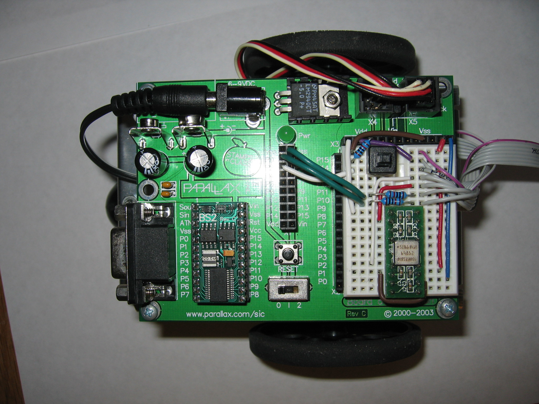
1)Insert the gyroscope in the protoboard attached to the Boe-Bot. At the top of the protoboard you will see a strip with 3 sections, Vdd, Vin, and Vss. Connect pin 1 to Vdd (+5) and pins 8 and 12 to Vss (ground), apply +15 to pin 13, and monitor the RATEOUT voltage at pin 2 with an oscilloscope or voltmeter.
2)To test the gyroscope, spin the Boe-Bot and observe the RATEOUT voltage, or apply a varying voltage (between 0 and 5 volts) to either pins 10 or 11. RATEOUT should rest at around 2.5v and vary between 0 and 5v relative to the angular speed or magnitude of voltage at pins 10 and 11.
Gyroscope Integrator and Signal Conditioner
The gyroscope outputs a voltage relative to the rate it is spun at. By integrating this rate we can get a voltage relative to the total angular displacement. LabVIEW can only get a value from the gyroscope every few milliseconds, and not always at consistent intervals. because we need a running total and very accurate results, will will need to design an integrating op-amp circuit.
The first step is to normalize the output voltage at zero so that the integrator doesn't amplify any noise of offset voltage. This will be done in two ways. The first is to use a difference op-amp to remove the bulk of the 2.5v offset, and then later we'll use a current summer to remove the remaining noise.
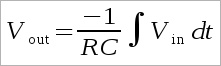
Once the signal has been roughly centered, another rough measurement of the range of integration is needed in order to design the op-amp integrator. The most the Boe-Bot will need to turn is ±180° to make any turn, so rotating by that much while integrating will give us our approximation. The equation for the output voltage of an op-amp integrator is:
Now that we know the integral of Vin over a 180° We need to pick our Resistor and Capacitor values so that Vout is between ±10v. For the integrator we will use a more accurate op-amp, the OPA177, and ceramic capacitors for their faster response time. Because the output from the first op amp isn't exactly zero, we will make a voltage divider out of a potentiometer and attach it to the non-inverting terminal of the op-amp integrator in a current adding configuration just like in the stand alone summing op-amps.
It is impossible to remove all noise from the circuit, so in order to prevent the integrator from accumulating large amounts of drift, a manual push button and a computer controlled reed switch will be added in parallel to the capacitors to discharge them and start the integration over at 0. A transistor is needed as the computer signal from the DAQ is does not provide enough current to trigger the reed switch.
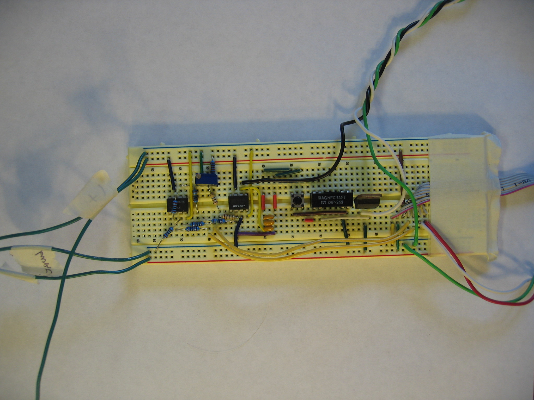
- Build a basic 1:1 difference op-amp on a separate breadboard using a LM741 op-amp and high quality 1kΩ resistors.
- The gyroscope has a constant 2.5v output at pin 7. Attach this to the non-inverting terminal and the RATEOUT voltage (pin 2) to the inverting terminal.
- Attach the output of the op-amp to the DAQ and build a simple LabVIEW program to take the integral over several seconds.
- Make several measurements while rotating the Boe-Bot through 180° and then calculate the value of RC for the integrator. Given the range of available ceramic capacitors, the resistor should be around 2MΩ. Report the average integral for 180° and the values you calculated for R and C in the lab report.
- Build the integrating op amp you designed using the OPA177 and high quality resistors. Use the output of the difference op-amp as the input for the integrator, and connect the output of the integrator to an analog input of the DAQ.
- Connect the two ends of a 10-turn 10kΩ potentiometer to ±15v and then connect the wiper to the inverting input of the integrating op-amp with a 20MΩ resistor.
- Add a pushbutton switch and a reed switch in parallel with the feedback capacitors of the integrator. The switch in the reed switch (at least, on ours) is between pins 1 and 7. Ground the coil of the reed switch (pin 6).
- Add a TIP31 transistor and give it +5v at the collector, connect the emitter to pin 2 of the reed switch, and attach the base to a digital output of the DAQ.
Wiring the Boe-Bot
1) So far the protoboard on the Boe-Bot should just have the wired up gyroscope. Included in the kit is a long ribbon cable, and should be the only wire coming off the robot. whether you have the signal conditioning circuit mounted on the robot or at the end of the ribbon cable with the DAQ is up to you. 2) Two wires in the ribbon cable will be needed to communicate between the Basic Stamp and the DAQ. They should be attached to two digital outputs of the DAQ and into the the BASIC Stamp inputs 0 and 1. Add some 1KΩ resistors to reduce the current to prevent burning out the BASIC Stamp. 3) Add a pushbutton flip switch on the protoboard to stop the BASIC motor control program. The open position (pin 1) should be wired to ground, the closed position (pin 2) should be connected to Vdd with a 1KΩ current limiting resistor, and the arm (pin 3) should be connected to the BASIC Stamp input 2. Cut off pins 4-6.Gyroscope Calibration (After Control Program and Motor Control is done)
Because the power supplies are never exactly the same, the signal conditioning circuit will have to be tuned each time the robot it powered up. The tuning can be done by either monitoring the output of the integrator with an oscilloscope, or by observing the output in your LabVIEW control program.
- Keep the Boe-Bot still and start monitoring the output of the integrator.
- Adjust the potentiometer until the output no longer drifts. use the pushbutton reset switch every so often, and when done, it should stay at just slightly fluctuating around 0v.
- Reset the Boe-Bot and slowly and smoothly rotate it by hand through 180°. The final voltage should read something just under ±10v. If it hits 10v before it has gone through 180°, you should increase the capacitance of the integrator by replacing the existing capacitor or by adding more in parallel. If it does not get near 10v, decrease the capacitance. Report the final capacitor and resistor values used in the integrator.
- Now that you have an approximate final value, divide it by the 180° you turned it through. This is now the value you need to multiply the voltage you read in from the DAQ in order to get the relative angle.
- Create a test in your control program to turn the robot 180°. Adjust the multiplier until the Boe-Bot accurately turns 180° each time. Report this value in your report as well.
Our Report
We went through a few different, but unnecessary steps compared to this condensed report. for example, rather than building the difference op-amp and then using LabVIEW to integrate the result, we built a more complicated LabVIEW program to sample, subtract, and then integrate the output right from the Boe-Bot. They both get the same result, but the one in the report cuts out unnecessary work, but does the same thing. We also made separate programs to get the final gyroscope calibration numbers, when we could have just waited till the control program was done and used that.
In designing our conditioning circuit, Niels went to professor Peshkin to get some advice and special parts. He suggested adding the potentiometer for tuning out noise, and i think its something we should learn in class as it's such a necessary tool for any sensor conditioning circuit. He also gave us the reed switch we used, the more accurate op-amp, the OPA177, and a brand new breadboard to reduce noise. For the RC circuit, we started by using 1MΩ and 6μF, but this turned out to be much too large, so by trial and error, ended up with 2MΩ and 2x0.047μF and 1x0.033μF. Then after calibrating with the control program, found the best multiplier to be (PUT THIS IN).